> PERMANENT OVERVOLTAGES
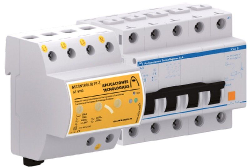
The protectors of the ATCONTROL / B series
they act when they detect an overvoltage
permanent firing emission coil
connected to them (S1, S2). This coil of
emission causes the switch to trip
associated automatic, protecting equipment
installed downstream.
The surge warning system
permanent consists of two indicators
green (correct mains voltage) and red
(overvoltage). It has a test button for
check that the installation has been carried out
correctly.
> TRANSIENT OVERVOLTAGES
The ATCONTROL / B protectors act
also when detecting a transient overvoltage
shifting current to ground and reducing
voltage at a level not detrimental to the
connected equipment.
Tested and certified as type protector
2 in official and independent laboratories
according to the UNE-EN 61643-11 standard and the REBT GUIDE BT-23. Suitable for teams of
categories I, II, III and IV according to ITC-BT-23 of the
REBT.
It has a thermodynamic device
disconnection from the mains in case
degradation and warning system
transient overvoltages. When the pager is
yellow, protector in good condition. If not, replace
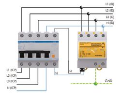
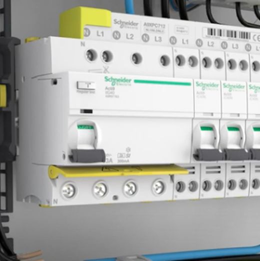
> INSTALLATION
Installs in parallel with the ground line
voltage, downstream of circuit breaker
included in the kit, with connections to the phases,
neutral and ground. Installation must be done without
tension on the line.
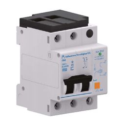
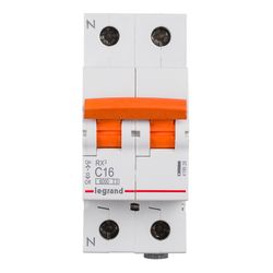
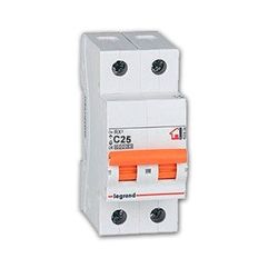
Circuit breaker is installed in series
with the line, enter the power control switch
power (ICP) and differential switch (ID).
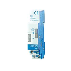
Connect terminals S1 and S2, always without
voltage, to the emission coil included in the kit.
This protector is self-configuring.
Automatically detects mains voltage
and self-programs the overvoltage limits
permanent in which it will act.
TECHNICAL DATA
Reference:
KIT ATCONTROL / B PT-T (25/32/40/50/63)
AT-8716 AT-8717 AT-8718 AT-8719 AT-8720
Nominal current: 25 A 32 A 40 A 50 A 63 A
Nominal voltage: Un 120 or 230 VAC
Maximum overvoltage: Uc 400 VAC
Actuation voltage: Ua 150 or 275 VAC
Actuation time: @ 150 VAC → 3 - 5 s / @ 230 VAC → 0.1 - 0.2 s
@ 275 VAC → 3 - 5 s / @ 400 VAC → 0.1 - 0.2 s
Nominal voltage of the emission coil: 110 - 415 VAC / 110 - 250 VDC
Cutting capacity: 6 kA
Type of tests according to UNE- EN61643-11: Type 2
Protection categories according to REBT: I, II, III, IV
Nominal discharge current (8/20 µs wave): I
n 15 kA
Maximum current (8/20 µs wave): I
max 40 kA
Protection level (1.2 / 50 µs wave): Up 1.4 kV
Protector dimensions: 72 x 90 x 80 mm (4 modules DIN43880)
Circuit breaker + coil dimensions: 88 x 81 x 65 mm (5 DIN43880 modules)
Circuit breaker cable range: Minimum / maximum section: 1.5 / 25 mm2
Coil cable range: Minimum / maximum section: 1.5 / 2.5 mm2
(single-line) or 4 mm2
(multifilar)
Protective cable range: Minimum / maximum section: 2.5 / 35 mm2
Tests certified according to standards: UNE-EN 50550, UNE-EN 61643-11, UNE-EN 60898
Application standards: UNE 21186, UNE-EN 62305


Muy bien, perfecto.
Buen precio y llego en el tiempo que me suelta
How do reviews and ratings work?
The opinions and ratings of the products are mostly made by registered customers who have purchased the product. These reviews appear with a "verified purchase" mark. In any other case this mark does not appear. The product rating, out of 5 stars, is calculated as the average of all published ratings for the product. To ensure the information is useful for other customers, reviews and ratings, whether positive or negative, are published after prior approval.